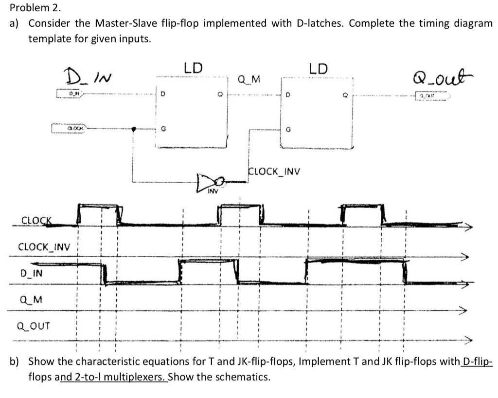
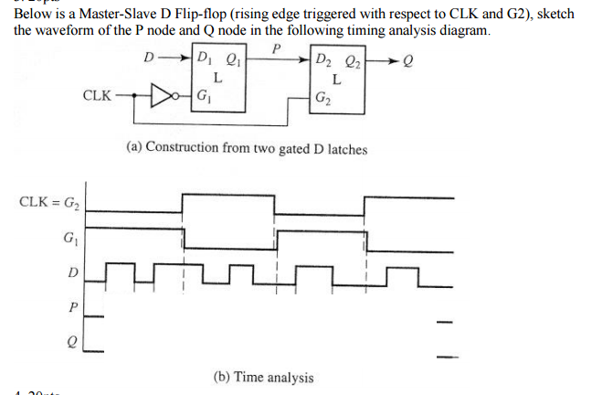
Have you ever wondered how digital circuits store and manipulate data so flawlessly, ensuring the smooth flow of information within complex systems? The answer lies, in part, within the ingenious design of a fundamental building block known as the master-slave flip-flop. This aptly named circuit acts as a digital latch, capturing data momentarily and holding it steady until the next command arrives. But how does this crucial task unfold? To understand the intricacies of data handling within a master-slave flip-flop, we must delve into the realm of timing diagrams, where the dance of signals unveils the secret workings of this elegant and essential circuit.

Image: www.chegg.com
Timing diagrams, much like the choreographed movements of a dance, illustrate the behavior of electronic signals within a circuit over time. They provide a visual representation, allowing engineers and designers to analyze the intricate relationships between input signals, internal states, and output responses. In the world of flip-flops, timing diagrams unveil the synchronized movements of control signals, data inputs, and output values, highlighting how data is latched and transferred within the circuit.
The Foundation: A Deeper Look at Master-Slave Flip-Flops
Master-slave flip-flops, often hailed as the workhorses of digital logic, are named for their two interconnected sections: the master and the slave. Each section comprises a basic flip-flop, fundamentally a latching mechanism capable of holding a single bit of information. Their unique arrangement forms the core of their functionality.
The Master: The Data Capturer
The master section, often described as the “data receiver,” diligently waits for a clock signal to arrive. Upon detection of a positive clock edge (transition from low to high), the master latches the data signal present at its input, ensuring it is stored within its internal circuitry. The master section can only accept new data when the clock signal transitions from low to high; otherwise, it remains unchanged, preserving the previously latched data.
The Slave: The Data Releaser
The slave section, the “data sender,” is intricately connected to its master counterpart. Unlike its master, it responds to the negative clock edge (transition from high to low). When this edge arrives, the slave mirrors the data currently stored within the master section, transmitting it to the output. This delay in response allows for a crucial data transfer: the master captures a new data value on the rising edge, and the slave releases the old data value on the falling edge. This ensures the integrity of data, preventing racing conditions and spurious signals from corrupting the data flow.

Image: www.chegg.com
Understanding Timing Diagrams: Deciphering the Signals
Timing diagrams serve as a visual language, providing a roadmap to the synchronized dance of signals within a digital circuit. In the context of master-slave flip-flops, understanding these diagrams is crucial for visualizing the data capture and transfer process, identifying potential issues and ensuring proper circuit operation.
Typically, a timing diagram for a master-slave flip-flop depicts several signals:
- Clock Signal (CLK): The heart of the operation, the clock signal dictates the rhythm of data capture and release. It is often represented by a square wave, with its transitions defining the moments of data transfer.
- Data Input (D): This signal represents the data to be latched by the master section and subsequently transferred to the output. Often displayed as a series of pulses or logic levels, it showcases the data values being manipulated by the flip-flop.
- Master Output (Qm): This signal represents the data stored within the master section. It changes only on the rising edge of the clock signal and remains steady until the next positive clock edge.
- Slave Output (Qs): This signal represents the data output of the flip-flop. It mirrors the master output but only changes on the falling edge of the clock signal, ensuring a synchronized data transfer.
Illustrative Example: Unraveling the Data Transfer
Let’s walk through a simple scenario to solidify our understanding of how timing diagrams illuminate the flow of data in a master-slave flip-flop. Imagine a basic circuit, where the data input (D) holds a logic ‘0’ at the beginning. As the clock signal rises, the master latches this value, and the master output (Qm) transitions to ‘0’. The falling edge of the clock signal has no effect on the master output, as it remains unchanged. Now, as the clock signal rises again, the master captures the newly arriving data input, which is now a ‘1’. The master output (Qm) now reflects this change, transitioning to ‘1’. The falling edge of the clock triggers the slave section, and the slave output (Qs) mirrors the master output, transitioning to ‘1’. This cycle continues, with the master capturing new data values on the rising edges and the slave releasing the previous values on the falling edges.
Real-World Applications: Where Data Latching Reigns Supreme
Master-slave flip-flops, with their ability to accurately capture and transfer data, are the unsung heroes behind countless electronic devices we use daily. They find applications in diverse fields, including:
- Digital Counters: Master-slave flip-flops are indispensable components in various counter circuits, particularly in synchronous counters where the data transfer occurs on the same clock edge. They enable a synchronized and precise counting mechanism, essential in controlling and measuring time intervals.
- Shift Registers: These circuits, crucial in data transmission and memory systems, use multiple flip-flops to shift data along a chain. Master-slave flip-flops ensure the synchronization of data movement, preventing data corruption and ensuring accurate information transfer.
- Digital Memory: Master-slave flip-flops serve as the fundamental building blocks of memory systems, responsible for storing and retrieving data. Their ability to retain information until explicitly modified makes them essential components in RAM circuits, allowing for temporary data storage.
- Data Acquisition Systems: In systems that collect data from real-world sources, like sensors or instruments, master-slave flip-flops are used to store and process data at specific times, filtering out unwanted noise and ensuring accurate data collection.
Enhancing the Functionality: Modifications and Advancements
Over time, engineers have made significant advancements in flip-flop design, incorporating various modifications to improve performance and optimize functionality. These enhancements include:
- Edge-Triggered Flip-Flops: These flip-flops, a refinement of the master-slave design, utilize a single clock edge to trigger both data capture and transfer. This eliminates the need for distinct master and slave sections, simplifying the circuit while maintaining the same functionality.
- JK Flip-Flops: This type of edge-triggered flip-flop simplifies the data transfer mechanism by combining data input and clock signal into a single signal, further streamlining the design.
- D Flip-Flops: Utilizing a single data input, D flip-flops offer a straightforward approach to data handling, directly transferring the data input to the output on the specified clock edge.
Timing Diagram Of Master Slave Flip Flop
Conclusion: The Power of a Simple Yet Critical Design
Master-slave flip-flops, with their simple yet elegant design, form the bedrock of digital logic, enabling a vast array of electronic devices to function flawlessly. The timing diagrams, like visual blueprints, unveil the synchronized dance of signals, illustrating how data is captured, stored, and transferred within these circuits. From data storage in memory systems to intricate data processing in digital counters and shift registers, master-slave flip-flops, along with their various modifications, remain essential building blocks in the realm of digital electronics. As technology continues to evolve, understanding the fundamental principles of these ubiquitous elements serves as a cornerstone for engineers, designers, and curious minds venturing into the world of digital circuits.


